UPS for my Wakeup Light
I designed a battery-powered backuppower supply to preserve my wake-up light's settings when the main power is disconnected. The UPS provides backup power enough to keep the clock running for several hours, preventing the need to reconfigure the clock and alarm after power interruptions. So I don't have to set the time again every time the power goes out.
Technical Details
The circuit has three main components:
- A battery
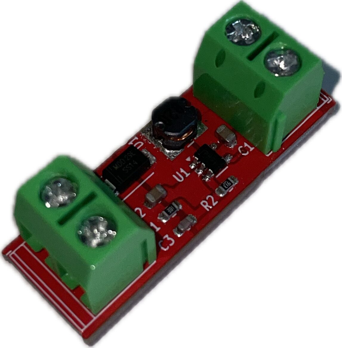
- A boost converter that increases the 3V battery voltage to ~23V DC
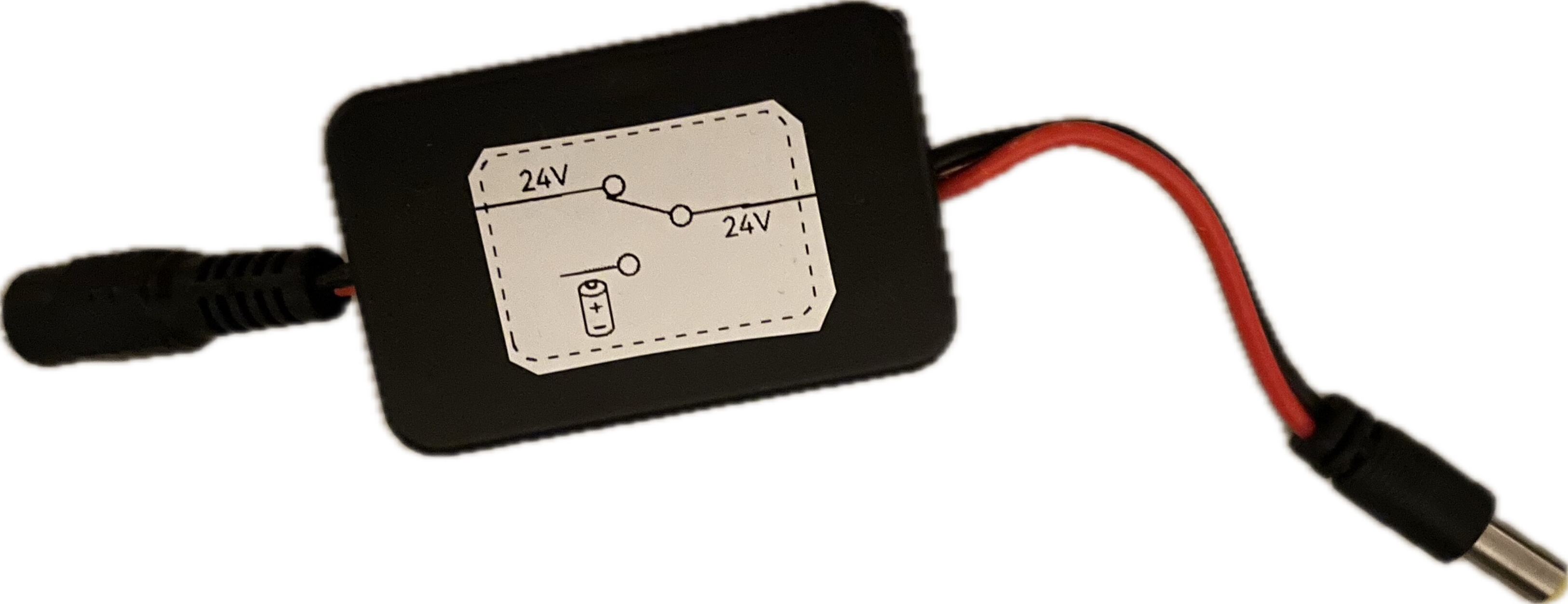
- A diode that automatically switches between main power and backup power
When main power (24V) is present, the diode blocks the lower backup voltage. If main power fails, the diode allows the backup power to flow to the light. This simple design ensures automatic power switching without complex circuitry.
24V DC] --> Switch{Auto
Switch} subgraph Circuit["UPS Circuit"] Batteries[Battery
3V DC] --> Boost[DC/DC
Boost] Boost --> |24V DC
Backup| Switch end Switch --> |24V DC
Continuous Power| Load[Wake-up
Light] %% Add styling to show mutually exclusive paths linkStyle 2 stroke-width:2px,fill:none,stroke-dasharray:3 style MainPower fill:#f5f5f5,stroke:#333 style Load fill:#f5f5f5,stroke:#333 style Circuit fill:#f9f9f9,stroke:#666,stroke-dasharray: 5
Future Improvements
I would like to add one of the following features:
- Low battery indicator, so that I know when I need to change the batteries.
- Or automatic battery charging when main power is restored, so that I don't need to change the batteries.
Here's a diagram of the planned improvements:
24V DC] --> Switch{Auto
Switch} Batteries[Battery
3V DC] --> Boost[DC/DC
Boost] Boost --> |24V DC
Backup| Switch Switch --> |24V DC
Continuous Power| Load[Wake-up
Light] %% New features with bright colors MainPower --> |New| Charger[Battery
Charger] Charger --> Batteries Batteries --> |New| Monitor[Battery
Monitor] Monitor --> |Status| LED[Low Battery
LED] %% Styling style MainPower fill:#f5f5f5,stroke:#333 style Switch fill:#f5f5f5,stroke:#333 style Boost fill:#f5f5f5,stroke:#333 style Load fill:#f5f5f5,stroke:#333 style Batteries fill:#f5f5f5,stroke:#333 %% Highlight new components style Charger fill:#e1f5fe,stroke:#0288d1 style Monitor fill:#e1f5fe,stroke:#0288d1 style LED fill:#e1f5fe,stroke:#0288d1 linkStyle 4,5,6,7 stroke:#0288d1,stroke-width:2px